
Block Diagram and Boundary diagram both are same, people use it interchangebly. So, Lets dive into the topic Block Boundary Diagram in detail.
What is Block boundary diagram?
Block diagram is the tool to demonstrate the overview of the system in broader view.
When we think about the any system, there is a lot of interfaces with other systems, either internal or external.
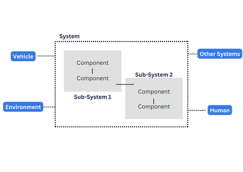
So, the this diagram will provide us the clarity of those interfaces and boundary condition of our system.
Purpose of Block/Boundary diagram
In the AIAG VDA FMEA, the 1st step is planning and preparation step. It is important to understand the project scope in this step.
And block diagram is the tool, which help to understand the scope of FMEA analysis. It shows the boundaries of our system and relation with other systems.
Therefore the purpose of the boundary diagram to give us the overview of our system and their relation/interface with other system explaining the project.
Block diagram is the powerful tool as a input for FMEA.
How to construct the block boundary diagram?
To construction of the block diagram can be vary company to company.
But at least you should follow some guidelines which will help to construct good block diagram.
You should create the block diagram using the brainstorming method with the help of CFT team.
Blocks/Elements
Create the blocks for the assembly/sub-assembly/components and arrange them as per the system structure.
Also consider the external systems as blocks to interact with our system/elements.
Linkage
Link those blocks with the appropriate lines. You can use different line styles to show the different linkage types.
Linkage type could be motion, clearance, direct contact, indirect contact, data flow, etc.
The arrow is also important to show the information flow between blocks. It is advisable to provide arrow at the end of lines to show flow.
In the linkages you should mention the types of connections
- Physical contact
- Material Flow
- Information/data transfer or Exchange of information for further processing
- Energy transfer
It can be more specific connection types such as,
Welding connection, Adhesive connection, Threaded connections, Physical contact, Electrical connection, Crimping, soldering etc.
Block boundary diagram with example

This is the boundary diagram for the computer mouse as a system. There are many sub-systems or external systems are interface with mouse.